Newer devices
Starburst Turret
How to build things like this
Robot
About Me
Compact Coilgun Parts and Construction
< Back to circuit information
Construction
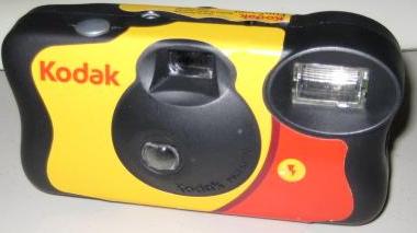
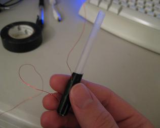
After I optimized my test coilgun a little bit and got it working well, I decided to try to squeeze it entirely inside a disposable camera case. A couple of friends suggested it, and I decided to do it because it's kind of like something Q from the James Bond movies would make. (If you think that James Bond is the coolest person in the 007 movies, then you're not an engineer, and you're also wrong. Because it is definitely Q.) Coilguns of this size aren't powerful enough to shoot at anywhere near lethal speeds, but if they were, I could totally leverage this into a job at MI6.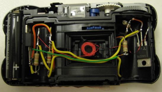
A charging circuit with one capacitor was already in the camera, of course, so I left that circuit in place and just soldered connections to it. The second capacitor, the resistors, and the SCRs fit in the compartments that normally hold film.
I hot-melt-glued the firing switch directly under the camera's picture-taking button, so that when the picture button is pressed down, it mechanically pushes on the firing button inside the camera. So pushing the camera's picture-taking button fires the coilgun.
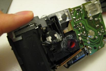
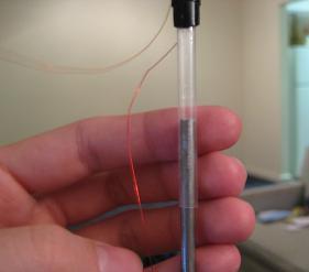
I had to cut the coil a lot to make it fit inside the camera case. I think I lost some of my accuracy by making such a short barrel, but it is still decently accurate (at 10 feet from a steady rest, a ten-shot group had a 5.5-inch diameter ). I attached the coil with hot-melt glue. First I tacked it in place with just a little bit of glue, so it could still be moved around. Then I held the camera still and tried to make the coilgun barrel point where the viewfinder was pointing, so the coilgun could be aimed accurately. When I got the coil lined up right, I applied a lot of hot glue around it to hold it in place.
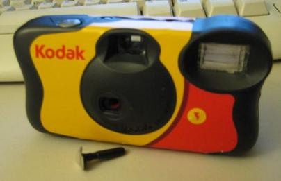
I had to remove the lens to let the projectile shoot through that hole. I wanted to make a cover for the hole that would look like a lens. So I took the removed lens, colored the back of it black, and glued it to a small plastic stick. I can stick that in the barrel, and the coilgun looks almost exactly like a disposable camera.
Parts
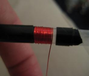
The coil in my coilgun is 36-gauge magnet wire from Radio Shack (around $5 in a pack with other magnet wire). It's wound around a drinking straw from the food court in the mall near the Radio Shack. To wind it, I wrapped electrical tape around the straw in two places, so that the straw formed a spool. Then I wound the wire onto that spool. I made three different coils; the best-performing coil had eight layers and was around 1.5cm long; that may not be the best possible, though.
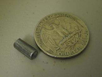
The projectile
To make a projectile, I took my drinking straw to Home Depot and looked at the metal rods. I chose the size that fit inside the straw the best. I also brought a magnet to double-check that the rods were ferromagnetic (they were steel rods, and steel is mostly iron, so they were. The projectile has to be a magnetic material or this type of coilgun won't work.) I bought one and cut a small length off to be the projectile. Bolt cutters would probably make the process really easy, but I don't have any, so I used a Dremel tool. It seems there is some optimization to be done with the length of the projectile. My best projectile was about 1cm long.
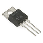
SCRs
My silicon-controlled rectifiers were the S6025L, which is $1.70 at Jameco.com. The datasheetfor it says it's rated for 25A continuous current, but can handle up to around 350A for a short surge. The coilgun firing is a short surge, and it's less than 350A (my coil resistance was about 4.5 ohms, so 600V/4.5 = 133A max, neglecting inductance, and it will decrease as the capacitors discharge). It took a little while to find the information I needed on the datasheet; probably one of the harder parts of this project was understanding the SCR datasheets enough to know which one to order.
Resistors
The "charging resistors" in my circuit were 1.5k ohm resistors that I had lying around. The exact value isn't very important. A value that's too high will make the Adam Smith Generator take a long time to charge, and a value too low will make it lose energy to the resistors when it's firing. I used 1/4 watt resistors rather than the normal 1/8 watt, because, on firing, if the capacitors can't discharge through the coil for whatever reason (like if it got disconnected), they will end up discharging entirely through the charging resistors over a few seconds (see circuit diagram on previous page). I was worried that the resistors might break or explode if that happened. So I intentionally tried that with the 1/4 watt resistors, and they seemed to handle it OK; they just got a little warm. Even though they were absorbing much more than 1/4 watt, it was only for a short time. So I think 1/8 watt resistors would probably work decently well too, but I haven't tried them.
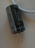
Capacitors
The capacitors are electrolytic photo flash capacitors from disposable cameras. They were 120 uF, rated for 330V. It's good to use capacitors with the same value for this circuit. Otherwise, you'll end up with the bigger capacitor still putting out current after the smaller capacitor has discharged, so the smaller capacitor will get reverse-charged a little bit. That's bad for electrolytic capacitors, as they're only supposed to get charged one way (the side that says "-" should always be the "-" side.) It will only be a brief, small effect though, so it's not a big deal if you can't get identical capacitors.
Getting disposable camera flash power supplies
The most popular way to get a current pulse for amateur coilguns is with a disposable camera's flash circuit. Those are excellent because they're free. Stores that develop film will have a bunch of used disposable cameras in a big recycling container, and they'll give you a bag of them if you ask.
The flash circuits use a single AA battery and step its voltage up through a transformer to charge a capacitor to 300V. They do that when you push the "charge" button on the camera. Then, when you take a picture, the camera shutter acts as a switch to supply a little current to make the gas in the flashbulb conductive. When the gas becomes conductive, the whole capacitor discharges through it, making the bright flash.
If you take apart a disposable camera, you'll see a AA battery that supplies the flash circuit; take it out. You'll also see a capacitor; it is most likely still charged to close to 300V. To make the circuit safe to work with, take metal pliers or something metal and short the two capacitor leads together. There will be a loud spark. Assuming you already took out the AA battery, the circuit won't be able to recharge the capacitor, and it should be safe to work with. Remember, if you take apart a camera, not to touch any metal parts until the battery is out and the capacitor is shorted. (This isn't one of those warnings you can ignore, like cooking meat thoroughly or washing your hands before returning to work. There is almost certainly a high voltage still on the capacitor, and it is connected to a lot of metal parts all over the camera. I accidentally shocked myself the first time I did this.)
Once you have the circuit, you can put the AA battery back in and push the charge button (which is conveniently on the circuit; the button on the camera just mechanically pushes the button on the circuit board). The circuit will charge the capacitor to 300V and then stop. On my compact coilgun schematic, the capacitor on the right is this capacitor, which I left in the circuit, and the capacitor on the left is another capacitor that I desoldered from another camera.